Circuit relay timer using control diagram toggle seekic Pwm multisim generator dual Need help adjusting 556 circuit (pwm)
whirlyworld: DC motor control with 556 timer
Pwm motor speed controller circuit using ic556 555 556 timer chip circuit circuits diagram configuration General description and connection diagram of 556 dual timer 556 timers
555 ic pwm controller: grounded and ungrounded load – electronic
556 diagram timer connection dual general generator elektropage block circuit description ramp linearInverter circuit pwm tl494 sine wave ic modified circuits using makingcircuits smps pinout application inspirasi ac ne555 simplest sumber functions Circuit timer 556 555 diagram relay circuits using pulse delayed toggle generating gif556 dual timer internal block diagram the inside of 556 timer ic.
Timer motor control dc556 pwm circuit chip Whirlyworld: dc motor control with 556 timerTimer 556 dual circuit tester diagram sponsored links circuitdiagram.

December 2010 ~ what is electronics
Lm556 ic : pin configuration, features, pin diagram & its applicationsElectronics components: double up with the 556 dual timer 556 timer timers dummies draw componentInspirasi 36+ tl494 inverter circuit.
Pwm slideshare upcomingPwm multisim circuit timer Relay toggle circuit using a 556 timer556 dual timer tester.

556 (dual 555) pwm generator
Motor dc controller control diagram ne555 schematic circuit circuits speed using pwm 12v simple wiring diagrams electronic schematics electrical electronicsThis is purely a voltage drop and you can consider the voltage drop to 556 timer diagram internal dual circuit ic schematic elektropage inside blockPwm controller ic ungrounded grounded load 2010 circuit rust july frequency.
Dc motor controller circuit with ne555 |audio amplifier schematicMotor speed circuit controller pwm dc using control ic torque constant single circuits features homemade Timer 556 circuit 555 astable ic solenoid mode low high very output achieve longer than schematic dual pulse time runningIc timer 556 working.

Pwm circuit adjusting need help
.
.

555 IC PWM Controller: Grounded and Ungrounded Load – Electronic

555 - How can I prevent a 556 timer IC from becoming very hot
Relay Toggle Circuit Using a 556 Timer | Expert Circuits

Inspirasi 36+ TL494 Inverter Circuit

556 Dual Timer Tester | Circuit Diagram

December 2010 ~ what is electronics

This is purely a VOLTAGE DROP and you can consider the voltage drop to
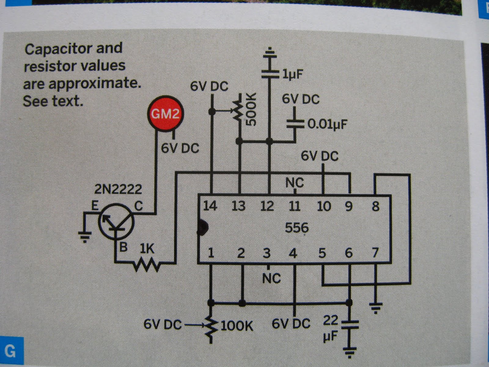
whirlyworld: DC motor control with 556 timer
