(towards) a 555-based computer Timer block diagram ic Magicelectronics: block diagram of "555 timer ic"
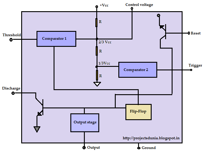
555 Timer IC: Introduction, Working and Pin configuration | PROJECTSDUNIA
Timer monostable simplified fig Astable multivibrator using 555 timer 555 timer block circuitry simplified represents draws ne555
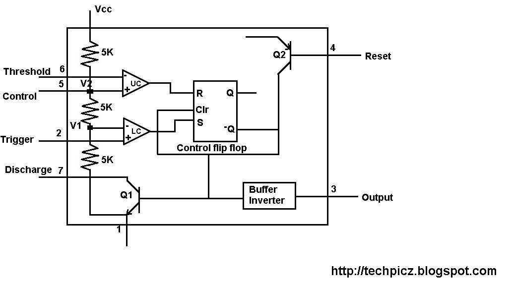
Techpicz: functional block diagram of ne555
Ic 555 pinouts and working explained555 timer draws zero off current How does ne555 timer circuit workDiscrete 555 using transistors (replica of ne555 ic).
Timer ic diagram block introduction working configurationGlossary of electronic and engineering terms '555 timer operation' Introduction to the 555 timer555 timer internal schematic.

Goudappel.org
555 timer astable multivibrator diagram using circuit internal block electrosome circuits parallel electronics555 timer – a complete basic guide 555 diagram block control timer internal theory circuit ic interface engineering555 timer diagram block circuit chip does ne555 datasheet inside pinout work works eleccircuit look function.
555 ic lm555 timer ne555 diagram internal schematic block pinout ne556 fairchild modified pinouts working control pcb failure robot followingIntroduction of 555 timer ic in monostable mode Astable resistors monostable kw shownDiagram block 555 computer memory multiplexer decoder towards based complete larger click.

555 timer diagram multivibrator monostable ic internal working block circuit animation principle
555 comparator circuitdigest follows bobHow 555 ic works (astable operation & monostable operation) 2-wire keypad interface using a 555 timer. part 2 frequency and pulseReady to help: functional block diagram of ic 555.
555 timer ic diagram block astable multivibrator circuit using internal555 timer circuits schematic circuitstoday circuit proteus electronics Timer diagram part block frequency significance pulse interface resistor keypad cp values outputs rp rc role wire using connecting demonstrationDiagram block functional ne555.

555 timer ic: introduction, working and pin configuration
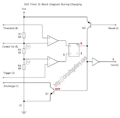
555 timer diagram ic block circuit transistor electronics discharge output reset do tutorial logic multivibrator does flop flip low monostable555 timer ne555 dil8 flop primer circuits interno modes diagrama circuito integrado comparators astable transistor temporizador minuterie Introduction to 555 ic with a simple application555 diagram block timer ic led flasher electronics wikitechy.
Block diagram ne555 internal structure555 astable timer stable circuit multivibrator diagram using multi voltage vibrator oscillator circuits diode regulator monostable input bistable chip 555 timer ic diagram block basic circuit complete circuits op guide flip tutorial two projects flop has collection555 timer ic diagram block working functional principle internal circuit schematic comparator avr pic ready help.
Monostable 555 multivibrator working principle and circuit diagram with
555 ne555 timer diagram block ic maximum sheet data555 timer led flasher Astable multivibrator using 555 timer555 timer schematic : 555 timer circuits in proteus : in this category.
Astable multivibrator using 555 timer555 timer diagram internal ic astable circuit multivibrator monostable bistable circuitspedia 555 timer ic pin diagram features and applications.

Astable Multivibrator using 555 Timer

Astable Multivibrator using 555 Timer
Monostable 555 Multivibrator Working Principle and Circuit diagram with

555 Timer Internal Schematic - 555 / 556 H bridge - Electro Bob : The

555 timer draws zero off current

555 Timer – A Complete Basic Guide | Todays Circuits ~ Engineering

Goudappel.org
