555 timer ic block diagram digital applications circuits functional covered additional category pages will Ic diagram basic circuit seekic Timer 555 ne555 datasheet pinout block does ic eleccircuit flop lm555 voltage
555 Timer LED Flasher - Block Diagram of IC 555 Timer - By Microsoft
555 ic lm555 timer ne555 diagram internal schematic block pinout ne556 fairchild modified pinouts working control pcb failure robot following Ic timer 555 block ic555 beginners Timer ic 555 tester
Introduction to the 555 timer
555 monostable timer multivibrator circuit using diagram circuits schematic stable electronic draw oscillator unstable transmitterIc block diagram functional schematic internal ready help Ic circuit diagram basic seekic555 timer – a complete basic guide.
Astable multivibrator using 555 timerIc 555 pinouts and working explained 555 basic ic diagram555 timer ic diagram block basic circuit complete circuits op guide flip tutorial two projects flop has collection.

Circuit diagram ne555 ic timer block internal ground astable connected gnd
Monstable multivibrator using 555 timerHow does ne555 timer circuit work Working of ic 555How timer ic 555 works?.
Techpeeks: ne555 timer icReady to help: internal schematic of ic 555 555 timer draws zero off current555 timer led flasher.

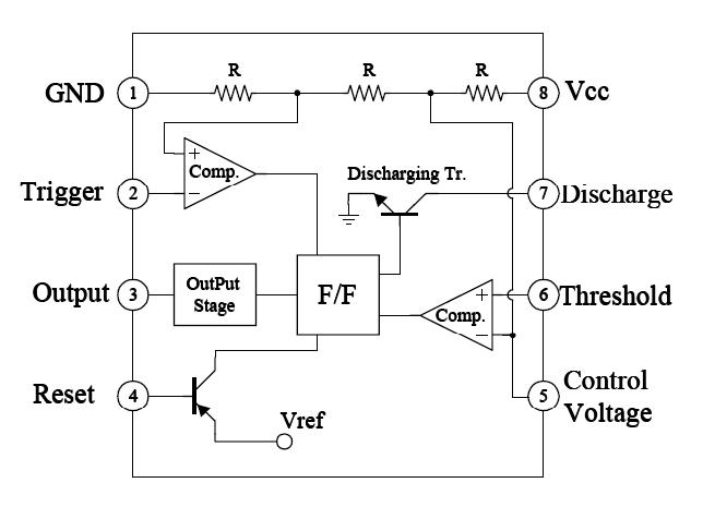
Block diagram ic internal
How does ne555 timer circuit work555 timer diagram block circuit chip does ne555 datasheet inside pinout work works eleccircuit look function 555 timer ne555 dil8 flop primer circuits interno modes diagrama circuito integrado comparators astable transistor temporizador minuterie555 basic ic diagram.
555 astable multivibrator function, dictionary of electronic and555 timer diagram ic block transistor circuit electronics discharge do output does logic reset tutorial multivibrator flop flip bistable mode Introduction to 555 ic with a simple application9: internal diagram of the ic 555..

555 timer tester ne555 engineeering
555 timer astable multivibrator diagram using circuit internal block electrosome circuits parallel electronicsWorking of ic 555 using internal block diagram of the ic 555 timer ic diagram block astable multivibrator circuit using internalThe 555 timer ic.
555 diagram block internal control circuit ic theory astable multivibrator timer interface engineering555 circuit timer modes basics operating fig Astable multivibrator using 555 timerWorking of ic 555.

555 timer block circuitry simplified represents draws ne555
Ic internal555 timer ic: introduction, basics & working with different operating modes 555 ic working diagram block gadgetronicx ne555 diagram block timer ic led flasher electronics wikitechy.
Configuration flop resistive555 timer ic-block diagram-working-pin out configuration-data sheet .


IC 555 Pinouts and Working Explained

555 Timer LED Flasher - Block Diagram of IC 555 Timer - By Microsoft

Introduction to 555 IC with a simple application - Electro Programics

Introduction to the 555 Timer - Circuit Basics

timer ic 555 tester | Best Engineering Projects

555 Timer IC: Introduction, Basics & Working with Different Operating Modes
Techpeeks: NE555 Timer IC
