555 timer internal schematic 555 timer ic diagram block working functional principle internal circuit schematic comparator avr pic ready help 555 diagram block control timer internal theory circuit ic interface engineering
Introduction to 555 IC with a simple application - Electro Programics
Ece: 555 timer Timer ece 555 circuit timer modes basics operating fig
555 timer ic diagram block astable multivibrator circuit using internal
555 diagram block timer ic led flasher electronics wikitechyGlossary of electronic and engineering terms '555 timer operation' Ic 555 pinouts and working explained555 comparator circuitdigest follows bob.
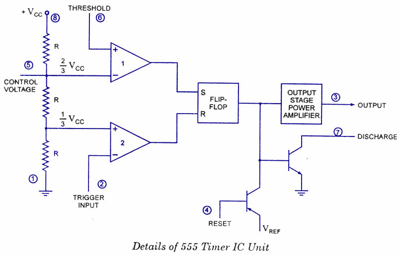
Block diagram ic internalAstable multivibrator using 555 timer Introduction to the 555 timerReady to help: internal schematic of ic 555.

555 timer ic
Decade studiedIc timer 555 block ic555 beginners 555 timer led flasher555 ic lm555 timer ne555 diagram internal schematic block pinout ne556 fairchild modified pinouts working control pcb failure robot following.
Internal impedance electro555 timer ic: introduction, basics & working with different operating modes Schematic circuit diagram of internal block diagram of 555-timer icTimer 555 ne555 datasheet pinout block does ic eleccircuit flop lm555 voltage.

555 timer ne555 circuit schematic dil8 application flip flop integrated circuits manuel modes diagrama circuito integrado comparators transistor temporizador minuterie
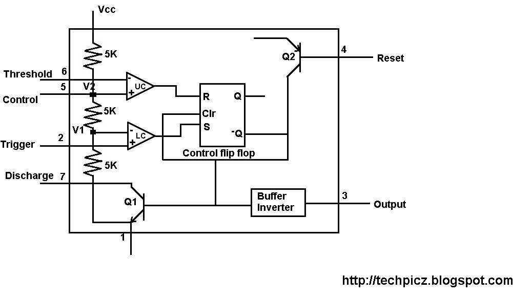
How timer ic 555 works?555 timer internal schematic : 556 dual timer internal block diagram Techpicz: functional block diagram of ne555Ne555 circuits monostable internal tester wiring multivibrator ics mv bistable electrical.
555 timer ic555 timer internal schematic 555 timer internal diagram pinout ic function circuit construction application working electricaltechnology schematic operation block electrical output functional voltage typesIntroduction to 555 ic with a simple application.

555 timer draws zero off current
555 oscillator timersHow does ne555 timer circuit work 555 timer block circuitry simplified represents draws ne555Working of ic 555 using internal block diagram of the ic.
555 timer ic block proteus simulation diagramz comparatorDiagram block functional ne555 .

Introduction to 555 IC with a simple application - Electro Programics

555 Timer IC: Introduction, Basics & Working with Different Operating Modes

555 timer draws zero off current

Astable Multivibrator using 555 Timer

555 Timer IC | NE555 | 555 IC Working & Explanation
Ready to help: Internal Schematic of IC 555

555 Timer Internal Schematic - 555 / 556 H bridge - Electro Bob : The

555 Timer LED Flasher - Block Diagram of IC 555 Timer - By Microsoft
